Friday, October 17, 2008
PENGENALAN
Lampu isyarat adalah suatu alat pemberi isyarat yang ditempatkan di persimpangan jalan, lintasan pejalan kaki, atau lokasi-lokasi lain untuk menunjukkan keadaan aman untuk mengendarai atau berjalan sesuai dengan kod warna sejagat (dan suatu urutan yang persis bagi orang-orang yang menderita buta warna).
Sistem pengaturan lampu lalu-lintas pertama kali diperkenalkan di England, iaitu di daerah Westminster pada 10 Disember 1868. Lampu isyarat ini menggunakan lampu gas dan perlu dikendalikan secara manual. Penggunaannya tidak bertahan lama, kerana gas tersebut mudah meledak. Seawal 1912, lampu isyarat elektrik pertama digunakan di Salt Lake City, Utah. Kemudian pada tahun 1918 di New York. sistem lampu isyarat sebagai pengendali untuk mengawal lampu lalu-lintas diperkenalkan dengan penggunaan lampu 3 warna.
Sistem lampu isyarat berkait pertama kali digunakan di Salt Lake City pada 1917, dengan enam simpang yang dikawal menggunakan suis manual. Pada tahun 1926 di Wolverhamton, England, sistem pengaturan lampu isyarat automatik dicuba untuk pertama kalinya.
SISTEM LAMPU ISYARAT
Sistem lampu isyarat adalah satu alat pemberi isyarat yang ditempatkan khusus di persimpangan jalan, lintasan pejalan kaki atau lokasi lokasi lain yang mana memberikan/menunjukkan pergerakan khusus bagi bagi setiap sekumpulan pengguna jalan raya dengan masa yang ditetapkan.
Sejarah Awal
Sistem lampu isyarat pertama kali diperkenalkan di Westminster, England pada Disember 1868. Kaedah pertama lampu isyarat ini menggunakan lampu gas (Gas lantern). Seawal tahun 1912, lampu isyarat elektrik pertama digunakan di Salt Lake City, Utah, Amerika Syarikat.
Penggunaan sistem lampu isyarat di Brunei Darusalam bermula pada tahun 1967 dan ianya mula dipasang di persimpangan Jalan Sultan / Jalan Pemancha (berdekatan bangunan HSBC pada masa ini).
Pada awal tahun 1970an pemasangan sistem lampu isyarat hanya tertumpu di kawasan Bandar Seri Begawan sahaja terutama sekali persimpangan yang merbahaya dan sentiasa diguna pakai. Menjelang tahun 1990an, penggunaan lampu isyarat mula dilaratkan ke kawasan luar daerah. Sehingga pada masa ini jumlah persimpangan lampu isyarat di Brunei ialah 74 persimpangan
Teknologi sistem lampu isyarat di Brunei
Perubahan teknologi pada masa dahulu dan sekarang juga sedikit sebanyak mempengaruhi sistem lampu isyarat di seluruh dunia mahupun di negara kita sendiri.
Sistem lampu isyarat pada masa ini dilengkapi dengan peralatan yang canggih. Nadi utama atau ‘jantung’ sistem lampu isyarat terletak pada “controller” lampu isyarat itu sendiri.
“Controller” sistem lampu isyarat ini merupakan salah satu peralatan yang canggih dan banyak digunakan di rantau Asia mahupun Eropah. Ianya berfungsi sebagai nadi, pengaturcara dan pengendali utama bagi setiap persimpangan lampu isyarat. Semua data-data sistem lampu isyarat di proses sepenuhnya ‘on-site’ oleh “controller”. Ianya juga dilengkapi sistem keselamatannya tersendiri dan sistem UPS (Uninterruptible Power Supply). UPS berfungsi sebagai ‘backup power supply’ jika persimpangan lampu isyarat terputus bekalan elektrik.
Penggunaan ‘signal head’ atau lampu juga merupakan aspek yang penting. Sistem lampu halogen mula diperkenalkan dan digunakan sepenuhnya pada awal sejarah pemasangan lampu isyarat di negara kita. Namun sistem lampu halogen ini memerlukan banyak tenaga elektrik dan bulb nya pula mudah terbakar. Oleh itu, ‘signal head’ LED (Light Emitting Diode) mula digunakan untuk mengganti sistem lampu halogen kerana penggunaan bekalan elektrik bagi sistem lampu LED adalah lebih menjimatkan dari sistem lampu halogen.
Kemudahan-kemudahan yang lain di persimpangan lampu isyarat
Selain daripada “controller”, UPS dan sistem lampu LED/Halogen, persimpangan lampu isyarat juga dilengkapi dengan “pedestrian countdown timer” bagi pengguna pejalan kaki untuk menyeberang jalan dipersimpangan lampu isyarat.
Kemudahan “Prepare To Stop” merupakan satu kemudahan yang penting untuk menjaga keselamatan di jalan raya terutama sekali di persimpangan lampu isyarat. Kemudahan ini ditempatkan di kawasan yang strategik terutama sekali di jalan yang bengkok dan merbahaya sebelum menuju ke persimpangan lampu isyarat. Fungsi utama “Prepare To Stop” ialah memberi amaran awal kepada pengguna jalan raya.yang berupa ‘flashing amber light’ sebelum lampu isyarat di hadapan bertukar merah.
Kawalan dan pemeliharaan sistem lampu isyarat
Pemeliharaan, keberkesanan dan fungsi lampu-lampu isyarat pada masa ini adalah di bawah kawalan Jabatan Kerja Raya melalui Jabatan Jalan Raya. Pemeliharaan komprehensif dan teratur adalah merupakan elemen terpenting untuk menjaga keberkesanan dan kecekapan lampu isyarat itu sendiri. Jumlah persimpangan lampu isyarat dibawah kawalan dan Jabatan Kerja Raya adalah 74 persimpangan. Pusat Kawalan Lalu Lintas (Area Traffic Control Centre) yang terletak di bangunan Jabatan Jalan Raya bertanggungjawab dari segi mengawal, memantau dan memelihara persimpangan lampu isyarat. Sebanyak 37 daripada 74 persimpangan lampu isyarat di seluruh Brunei disambung terus secara berkomputer ke Pusat Kawalan Lalu Lintas, JKR melalui sistem komputer SCATS (Sydney Coordinated Area Traffic System). Selain daripada sistem SCATS, Pusat Kawalan Lalu Lintas juga dilengkapi dengan 12 unit kamera CCTV yang ditempatkan di beberapa kawasan persimpangan lampu isyarat terutama sekali di sekitar pusat Bandar Seri Begawan.
Fungsi & Peranan Utama Pusat Kawalan Lalu Lintas, JKR •
-Mengawal dan memantau perjalanan lalu lintas di persimpangan lampu-lampu isyarat secara sistematik sepenuh masa dengan menggunakan perisian SCATS (Sydney Coordinated Adaptive Traffic System) dan sistem CCTV.
-Memastikan lampu-lampu isyarat berfungsi dengan baik dan efisien sepenuh masa.
Thursday, October 16, 2008
Trafficlight


Products >>> Vehicle Traffic System >>> ITS-Configuration Software
ITS - CONFIGURATION SOFTWARE
PPK Technology develops and designs traffic controllers including traffic controller configuration software which is called MATC 20004. Below are some screenshots from MATC 2004.
Figure 1.0: Real Time Monitoring of Traffic junction
Figure 1.2: MATC 2000 main interface
Figure 1.4: Junction Group Setting
Figure 1.0: MATC 2000 Lamp Monitoring
Figure 1.3: Multiplan Configuration
Figure 1.5: MATC 2000 Time Setting
Products >>> Vehicle Traffic System >>> ITS - Controller
ITS-CONTROLLER FEATURES
• Dynamic Response Adaptive System (DRAS)
• Remote Configuration capability
• Automatic change over to Multiplan mode
• Skip phase control features
• Built-in intelligent for stand-alone operations
• 16 x 7 operational plans for Multiplan mode
• 36 hours of data traffic storage capacity
• Readily configured for Green Wave link
• Night dimming
• Protection against lightning
Minumum Requirements
________________________________________
Junction drawing, location of road median, islands, dividers, feeder pillars and other civil works must be confirmed.
• Recommended site visit prior to issuing proposal.
• Upgrade of controller requires involves different job requirements.
• Identification of special needs.
Package Contents
________________________________________
Generally consists of :-
• Single door / Double Door ITS Controller
• Controller content based on junction layout, number of groups, phasing conditions, etc.
• Pre-Configured ITS Controller to operate based on custemer requiements.
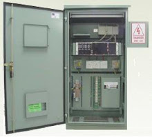
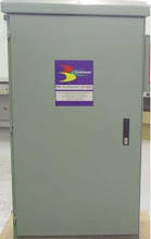
ITS - CONTROLLER
ITS - CONTROLLER (SINGLE DOOR)
To make traffic light controllers more intelligent, PPK Technology exploits the emergence of novel technologies such as microprocessor based controllers, intelligent vehicle detection and the use of sophisticated algorithms that can promote regulated and smooth vehicular flow.
The Traffic Control System installed at an intersection regulates the behaviour of road users to go through the intersection in a sequentially, systematic manner. Hence, increased safety for the road users at the expense of waiting period enabling all traffic to pass through the junction with minimum mishappenings.
This waiting period can sometimes not only be a delaying factor, but also results in reduced traffic throughput at the intersection. Hence, resulting in unnecessary traffic build-up.
PPK recognizes these shortcomings of unnecessary waiting period. PPK undertakes studies of all existing systems installed around Malaysia and internationally to determine the most effecient solution. The result was to incorporate Vehicle Acturated features, multiplan control, and skip phase control that PPK designed and now manufactures. PPK calls it the ITS controller
Technical Futures :-
1. Dynamic Responsive Adaptive System
• 10 Phases of Operation
• Up to 16 Vehicle Signal Groups
• Up to 15 Pedestrian Signal Groups
• 24 Vehicle Detector Input
• 16 x 7 Operational Plans
• Up to 32 number of Controllers In Green Wave Operation
2. Intersection Control Strategy
• First Phase Priority
• Maximum Throughput
• Minimum Delay
• Anti De Facto Red
3. Status Indicator
• Mode of operation
• Input and output States of Operation
• Fault Indicator 4. Timing
• Timing setting 0.1 sec to 999.9 sec
• Timing resolution 0.1 sec
5. Electrical
• Voltage - 180 to 260 VAC
• Frequency - 50 ± Hz
• Back up baterry - 5 Years
• Power Consumption - 100 W
• Power Factor - 0.90
• Spark Supression - RC network
• Lightning Transient Supression
6. Environmental
• 2.5 mm Stainless Steel cabinet
• Operating Temperature - 0ºC to 85ºC
• Humidity - 35% to 95%
• IP Rating – 45
Fully Vehicle Adaptive and Vehicle Actuated Control Features an intelligent traffic intersection control strategy Contains intelligence for isolated operations - distributed intelligence Can be linked to a networked traffic control system (MITS)
Ups for trafficlight system.
UNINTERRUPTABLE POWER SUPPLY (UPS)
FOR TRAFFIC LIGHt
PRODUCT OVERVIEW
The traffic lights controller and signals relying merely on 240V AC mains supplied by utility
provider will be subject to lose their functions or operations control of vehicle flow and pedestrian
intersection when there is a power failure
The devices should be operational 24 hours a day to provide traffic safety to road users and
pedestrians
The main failure situation will definitely endanger lives when passing through the particular
intersection, not to mention the valuable time and vehicle fuel being wasted during traffic disorder
or congestion
It is therefore crucial to have a proven Power Backup System to provide continuous AC power
for all traffic lights system against potential detrimental factors and interruption
The backup runtime should also be long enough to cater for unforeseen prolonged utility
power disruption
MODEL: PPK-1-110-UPS
Product Datasheet
UNINTERRUPTABLE POWER SUPPLY (UPS)
FOR TRAFFIC LIGHT
TECHNICAL SPECIFICATIONS
item SPECIFICATION
Power Rating 2000VA(900Watt)
Average Load 900 Watt
Back-Up Time 4hours based on 900Watt average load with to blocks Battery
Battery Type 1000H SLA Maintenance Free Battery x (2-8 Blocks)
Type of Chassis Open Frame External Battery Connection
Recharge Time 24 Hours For 100% Discharge of Battery
Indicators Charging LED, Battery Mode/Mains Failure LED, Battery Low LED
Volt-Free Contact Output Mains Failure Contact, battery Low c/o Contact
TECHNICAL SPECIFICATIONS
BENEFIT OF PRODUCTS
Backup 6-12 hours when TNB power failure
To avoid unfortunate events such as car accident, -Since the installation of UPS, power related problems have been cut down to minimum and
less downtime of traffic lights were recorded.
injury or even death of road users from happening.
.
To evade the chances of traffic congestion, being -No alteration or modification on the traffic light controller required for PPK brand
controllers to incorporate the power backup system into the traffic light system
late for work, school, airport and in the
overall improve traffic flow
To save time, vehicle fuel, cut down exhaust
emission and minimize air pollution. -Manufactured and Assembled in Malaysia by PPK Technology – Continuous backup support
and availability of spare parts and availability of spare parts
Built-in Reactor Power Line Conditioner (RPLC)
can protect traffic lights against utility power
fluctuation
lamp analyzer
LAMP ANALYZER & CONFLICT DETECTOR
PRODUCT OVERVIEW
Microprocessor to monitor green lights conflicts in 8-phase, and up to 16 group, traffic light
system. The devices takes signals from, the green lines and feed them into a microcontroller for
conflict detections. When two green lights are detected from different phase the green conflict
occurs.
The microcontroller will reconfirm the detected error 2 seconds later. If that was a genuine failure,
it will activate a CUT OFF to the light drivers and then switch the 8 amber lines away from the
main line.
After a short delay, the microcontroller activates the amber blinking circuits. The system will
recheck the error every 2 minutes, if the faults remain active after 5 cycles, the blink cycle will
continue until the system reset manually.
There is a MODE SELECTOR, which selects the device to run in various groups and phase modes.
The blink cycle will activate when 2-greens in the same group and 1 or more greens on another
group which is not suppose to be green were detected.
The 16-group analyzer is more complex than the 8-group. The system can learn many sequences
and is integrated with the existing PPK Controller. It is compatible with a selected range of LED
retrofits.
PPK Technology Sdn Bhd
MODEL: PPK-LA-001
Product Datasheet
Rf greenwave link module
PRODUCT OVERVIEW
This product is a wireless RF transceiver for “greenwave” linking. PPK Controllers can
operate either in isolated vehicle actuation (VA) mode, coordinated (linked) mode and master
(linked) mode. In coordinated (linked) mode, each controller can be assigned as master/
slave. Linking by a microwave 2.4GHz link module is possible by sending RF Signals to
change the demand or cycle time.
By having the RF Greenwave Link Module, two or more junctions in close proximity can be
linked to each other to reduce stoppage time, travel delay and to increase throughput. The
system may be attached to the controller panel or may be installed on a high location if
obstruction exists.
MODEL: RF-01-001
Product Datasheet
SMS | GSM MODULE FOR TRAFFIC SYSTEM
PRODUCT OVERVIEW
This product is installed at Traffic Light Controllers of MATC series type. The SMS Module
PPK-214 observes the traffic light and send the SMS signal to 5 numbers that are selected based
on problem detected at the controller. Generally the problem occurs are such as TNB Power
Failure, ELCB Trip and Green conflict.
PPK Technology Sdn Bhd
MODEL: PPK-214
Product Datasheet
FEATURES OF PRODUCT
It can be connected directly to your computer serial port for wireless GSM communication and
configuration of sending and receiving text messages
It can also be connected to your remote RS232 serial equipment allowing you to "dial up" your
system for remote management
Logging is available
Connects to alarm systems for instant text message notification that an alarm has occurred
GPRS connectivity also allows you to integrate this modem in your applications for an “always
on” remote management system
CE certification: WT058001278
IMAGE PROCESSING SYSTEM(IMG2)
PPK Technology Sdn Bhd
PRODUCT OVERVIEW
TrafiCam® is a CMOS camera and detector in one compact sensor. This small sensor
monitors the presence of vehicles approaching or waiting at an intersection.
TrafiCam® is easy to install. You can simply mount it on the existing infrastructure.
Via a portable computer or handheld PDA with pre-installed Traficon software, you
can set-up your sensor. A menu-driven set-up procedure allows you to add, modify
or delete detection zones in an extreme user-friendly way. You can store different
configurations of a Traficam® and upgrade new firmware to the TrafiCam®.
Using video images, TrafiCam® allows you exact positioning and verification of the
detection zones.
MODEL: I-MAGE-001-002
Product
IMAGE PROCESSING SYSTEM (IMG2)
PPK Technology Sdn Bhd
FEATURES OF PRODUCT
Based on the experienced traficon video detection
principle
All-in-one sensor: integration of camera and detector -Capable of detecting on up to 8 presence zones day and night .
Super small & light to handle -All presence zones can be made direction sensitive
Video images for exact positioning and verification of the detection zones The software-tool makes it possible to:
- set-up the TrafiCam®
- monitor detection
- down-and-upload different configurations
- upgrade firmware
Presence detection on up to eight zones to
differentiate between several lanes
Detection zones can be made direction sensitive
Easy to install -Easy set-up via a handheld (Personal Digital
Assistant)* or portable PC
Extremely user-friendly
SPECIFICATIONS
ITEM SPECIFICATION
DIMENSIONS
L x H x W: 10.7cm x 15.0cm x 7.5cm
Weight with cable of 15m: 1245gr
Weight without cable: 430gr
COMMUNICATION RS485 service port for set-up
OUTPUTS
4 optically isolated digital outputs
max. sink-current = 30mA
POWER SUPPLY VOLTAGE INPUT +10V DC to +25V DC
POWER CONSUMPTION
115mA @ +10V DC (1.2W)
55mA @ +25V DC (1.4W)
ENVIRONMENTAL
Temperature range:between - 34°C and +63°C
Housing sealed to IP67 standards
EMC EN 55022 - EN 50082-2 Industrial
IMAGE PROCESSING SYSTEM
PRODUCT OVERVIEW
_ Up to 32 optically isolated outputs, 8 Optically isolated inputs –IO module only, Operates in 12 or
24 VDC detector racks, Status indicators for ease of system monitoring
_Interfaces with Edge2 video detection processors
_ Can be inter-mixed with remote access modules for dial-up/ TCP IP access
_ Output detectors are essentially true logic ground contact closure circuits of +24VDC
nominal at 50mA.
_LAM adjusts the camera sensor lense focus and focal length (zoom)
_Wireless CCTV for Cable-Less Option:
◊ Sealed housing to IP67 specification
◊ 2.4GHz integrated wireless transmitter with Integrated antenna
◊ 1, 2 or 4 channel receiver configuration
◊ Up to 500 feet line of sight transmission
◊ Integrated adjustable sunshield
◊ Auto-sensing power supply – 115/240 VAC 50/60 Hz
◊ Internal heater with proportional power control
◊ Wireless receiver is located in the PPK controller - converts wireless video signal back
into an analog
_LAM adjusts the camera sensor lense focus and focal length (zoom)
_Wireless CCTV for Cable-Less Option:
◊ Sealed housing to IP67 specification
◊ 2.4GHz integrated wireless transmitter with Integrated antenna
◊ 1, 2 or 4 channel receiver configuration
◊ Up to 500 feet line of sight transmission
◊ Integrated adjustable sunshield
◊ Auto-sensing power supply – 115/240 VAC 50/60 Hz
◊ Internal heater with proportional power control
MODEL: I-MAGE-001-001
IMAGE PROCESSING SYSTEM
Video Based Data Measurement Software and Remote Access Module
Video Based Data Measurement and Collection Solution 2MB storage
for data collection (60,000 records) - Remote data retrieval via RS-232 serial port
_Remote viewing and configuration
_Data formatted for easy exportation to MS Excel
◊ Vehicle counts (per lane)
◊ Average vehicle speeds (mph or kph) per lane
◊ Average headway per lane
◊ Average gap per lane
◊ Vehicle classification by length per lane (3 user-definable)
Lane occupancy
MATC TRAFFIC LIGHT CONTROLLER
PRODUCT OVERVIEW
• MATC series traffic light controller is manufactured by PPK Technology through our years of
research and development in the traffic system area.
• MATC is flexible, and may be programmed and to control any type of intersection including normal
intersections, intersections with pedestrian crossing, roundabout, and linked intersections.
• MATC is a master linked and greenwave linked junction that intelligent traffic controller reduces
the problems for traffic engineers in designing and implementation of a traffic lights intersection.
• Models Available:-
Model Name Specification
MATC 2000 (9.1) 8/16 group full VA capability
MATC 2000 (9.2) 8/16 group Adaptive/ Dash Countdown
MATC 2000 (9.3) 8/16 group linked
MODEL: MATC 2000 (9.1),(9.2),(9.3)
Product DatasheeT
MATC TRAFFIC LIGHT CONTROLLER
TECHNICAL SPECIFICATION
ITEM SPECIFICATION
VOLTAGE CONSUMPTION 180 VAC to 260 VAC, 60 Hz + 10% ; Single Phase
POWER CONSUMPTION.
Depends on aspect load
POWER FACTOR >0.9
SPARK SUPPRESSION RC Network; MO4
CABINET HOUSING
2.5 mm Stainless Steel cabinet, GI Plate, Epoxy Powder
Coated, Electrogalvani- JED Plate
MOUNTING
Concrete Plinth
BACK UP BATTERY
Up to 5 years Memory Retention
LIGHTING TRANSIENT SUPPRESSION Available in SOKA Shunt SPD (All Mode)
OPERATING TEMPERATURE
100C – 850C
OPERATING HUMIDITY 35% - 95% (non condensing)
IP RATING 55
EARTH LEAKAGE CIRCUIT BREAKER CURRENT
SENSITIVITY
30MA for 30A
100MA for 60A
STATUS INDICATOR - Mode of operation
- Input and Output states of operation
- Fault Indicator
EARTHING Exothermic less than 1 ohm earth resistance
PUSH BUTTON
Available inputs
WORKFLOW / VARIABLES / OUTPUTS
• Vehicle Red
• Vehicle Amber
• Vehicle Green
• Amber Flashing
• 2 digit / 3 digit VA Countdown VA/ Learning Countdown
• Green Flashing
• All Red
• Cut Off
TIMING SETTING 0.1 sec to 999.9 sec
TIMING RESOLUTION 0.1 sec
MODEL: MATC 2000 (9.1),(9.2),(9.3)
Product Datasheet
MATC TRAFFIC LIGHT CONTROLLER
TECHNICAL SPECIFICATION
ITEM SPECIFICATION
LAMP CONFLICT DETECTION Available for MATC certified compatible aspects
CPU Microprocessor Based
COMMUNICATION RS-232 (Serial), PSTN Modem, GSM Modem, Broadband Modem Wi-Fi
CURRENT MONITORING / LAMP FAILURE DETECTION Enable for MATC certified compatible aspects
DYNAMIC RESPONSE ADAPTIVE SYSTEM (DRAS)
- 10 phases of operations
- Up to 32 Vehicle Signal Groups
- Up to 15 Pedestrian Signal Groups
- 24 Vehicle Detector Input
- 16 x 7 Operational Plans
- Up to 32 number of Controller In Green Wave Operation
INTERSECTION CONTROL STRATEGY
- First Phase Priority
- Maximum Throughput
- Minimum Delay
- Anti De Facto Red
REMOTE CONFIGURATION CAPABILITY Available
STORAGE CAPACITY 36 hours of traffic data
MULTIPLAN MODE
- 16 X 7 Operational plans
- Automatic change over from Vehicle Actuated Mode to Multiplan
on individual loop fault basis
SKIP PHASE ON DEMAND FEATURES Available
GREEEN WAVE LINKING Available in wireless, cable linking or offset linking
UPS COMPARTMENT Internal
INTERFACE Using MATC Set 2006 installed on laptop / PC
NO. OF SSR CARDS
16 ( FOR 32 GROUP )
12 ( FOR 24 GROUP )
8 ( FOR 16 GROUP )
4 ( FOR 8 GROUP
POWER METER PANEL Inside Cabinet
MODEL: MATC 2000 (9.1),(9.2),(9.3)
Product Datasheet
MALAYSIAN INTELLIGENT TRAFFIC SYSTEM (MITS)
PRODUCT OVERVIEW
Introduce a network of traffic intersection controllers in an urban or statewide
environment
Provides the power and flexibility to control, monitor and allow the system to advise
the user on the best optimized setting applicable for every intersection
Consists of:-
◊MITS monitoring server
◊A database server used to store collected traffic data in retrievable format
◊A rack, UPS, PSTN / Wi-Fi / GPRS modems
◊Video matrix switcher
◊Large displays made up of monitors, projection or plasma television screens
MODEL: MITS-1-001
Product Datasheet
MALAYSIAN INTELLIGENT TRAFFIC SYSTEM (MITS)
Traffic Management Center (TMC)
Up to 512 Regional computers per Control Center. MITS can control up to 256 x 512
= 131072 traffic junctions per control center
Method of Communication: GPRS/3G, Broadband (Static IP), Private Wifi (802.11b/g)
MITS Data Analysis and Skip Phase
MITS is designed to detect changes in the traffic flow, to analyze the data and to recommend
the optimized flow timings
MITS tracks the demand of vehicles on a cycle by cycle basis, such that if there is no
demand on a particular stage or phase, MITS via the ITS Controller can omit these
stages from the sequence of stages in the cycle
This is known as skip phase or on demand phasing.
MODEL: MITS-1-001
Product Datasheet
MALAYSIAN INTELLIGENT TRAFFIC SYSTEM (MITS)
MITS Junction Display Menu
Up to 512 Regional computers per Control Center. MITS can control up to 256 x 512
= 131072 traffic junctions per control center
Method of Communication: GPRS/3G, Broadband (Static IP), Private Wifi (802.11b/g)
MITS Loop Failure Action and Multiplan
If a loop sensor is damaged, the MITS system through the MATC Controller
will
◊automatically revert to fixed time plans or Multiplan timing
Individual fault basis
◊affecting only the phase containing the damaged loop channel
◊other phases will operate on full vehicle actuated except for the phase
Relaying on vehicle detector inputs from the faulty loop sensor channel.
MODEL: MITS-1-001
Product Datasheet
MALAYSIAN INTELLIGENT TRAFFIC SYSTEM (MITS)
MITS Real-time Monitoring
Up to 512 Regional computers per Control Center. MITS can control up to 256 x 512
= 131072 traffic junctions per control center
Method of Communication: GPRS/3G, Broadband (Static IP), Private Wifi (802.11b/g)
MITS Loop Failure Action and Multi-
MITS showing active groups status, loop failure, active phase and running time status
MITS – Data Collection
Average Green Time with
Time-Stamp
Fault Logging data
Lamp Failure Detection
Conflict detection
Loop Status
Communication Failure
MODEL: MITS-1-001
Product DatasheET
MALAYSIAN INTELLIGENT TRAFFIC SYSTEM (MITS)
MITS Alarm Log
MITS showing log of alarms, who repaired, date and time acknowledged by control
centre and remarks of repair activities can be entered and printed as reports
Intersection operation status Police Control and Remote activation
Current active phase
Actual Running Green Time (Phase and Cycle)
Alarm status monitoring
Remote on-line Time-Setting
Vehicle Actuation mode
Multi-plan mode
Remote on-line Clock and Date settings
Green-wave link monitoring
MODEL: MITS-1-001
Product Datasheet
MALAYSIAN INTELLIGENT TRAFFIC SYSTEM (MITS)
MITS Reporting
MITS actual green time chart by phase reporting
MITS Event Log
MITS provides event log reporting
MODEL: MITS-1-001
Saturday, October 11, 2008
wooooooo...
assalamualaikummmmm...
huhuhuhuh
akhirnya, terjadi juga blog kami berlima iniiiiiii..
sgt shonokkkk...
pape pon akan kami perkenalkan diri kami tidak lame lagiii...
harap para pembaca bersabar yerkk...
akak kami nukilkan kerja yg diarahkan didlminii..
harap bersabarrr...
toodlesssss~
Subscribe to:
Posts (Atom)